Select One Color Between Two Mirrors: A Fabry–Pérot Narrowband Filter
Two high-reflecting mirrors placed together seem as though they should block even more light. Yet when the round-trip phase between them is just right, the transmitted waves interfere constructively and open a very narrow transmission peak inside the high-reflectance band. A Fabry–Pérot narrowband filter uses this effect to select a specific color.
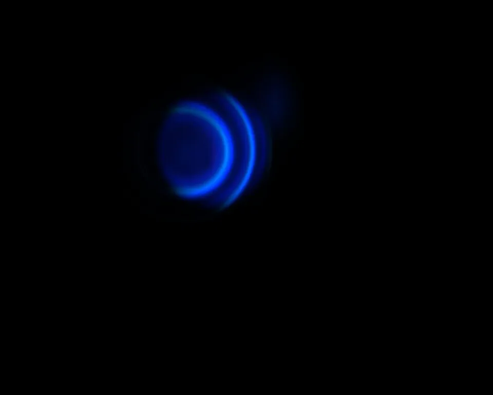
Real interference rings formed by cadmium-lamp light passing through a Fabry–Pérot etalon (Source: Sai2020 / Wikimedia Commons · License: Public Domain)

This tutorial builds that transmission peak near 550 nm. You will calculate the cavity thickness, configure two mirror-symmetric DBRs, and evaluate the filter using peak transmittance, full width at half maximum (FWHM), and Q factor.
The Half-Wave Cavity Condition
Section titled “The Half-Wave Cavity Condition”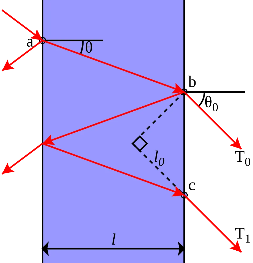
Multiple reflections and transmitted beams inside a Fabry–Pérot cavity (Source: Krishnavedala / Wikimedia Commons · License: CC0 1.0)

The red rays show the transmitted beams produced after repeated round trips between the two reflecting interfaces; $\theta$ is the propagation angle inside the cavity. The derivation below begins with the normal-incidence resonance condition.
At normal incidence, the basic cavity resonance condition is
$$ 2n_cd_c=m\lambda_0 . $$
Here, $n_c$ is the cavity refractive index, $d_c$ is its physical thickness, $m$ is a positive integer resonance order, and $\lambda_0$ is the vacuum resonance wavelength. For an MgF₂ cavity with $n_c=1.38$, $m=1$, and $\lambda_0=550\ \mathrm{nm}$,
$$ d_c=\frac{550\ \mathrm{nm}}{2\times1.38}=199.28\ \mathrm{nm}. $$
This is a half-wave optical thickness. The DBRs add reflection phase, but for this symmetric quarter-wave construction, 199.28 nm places the transmission peak exactly at 550 nm.
Mirror-Symmetric Layer Order
Section titled “Mirror-Symmetric Layer Order”Build the following structure from air to the glass substrate:
| Region | Layer order | Repeats |
|---|---|---|
| Front mirror | MgF₂ 99.64 nm / TiO₂ 56.12 nm | 4 |
| Cavity | MgF₂ 199.28 nm | 1 |
| Back mirror | TiO₂ 56.12 nm / MgF₂ 99.64 nm | 4 |
| Substrate | Glass, 1 mm and incoherent | 1 |
The front mirror starts with low index and ends with high index. The back mirror starts with high index and ends with low index. Both cavity-facing layers are TiO₂, making the complete stack mirror-symmetric about the cavity center.

Symmetric DBR–cavity–DBR stack on the Structure page
Click Edit Group for the front mirror. Confirm MgF₂ 99.64 nm → TiO₂ 56.12 nm with Repeat Count set to 4.

MgF₂/TiO₂ unit for the front mirror in Edit Group
Open Edit Group for the back mirror. Confirm the reversed order, TiO₂ 56.12 nm → MgF₂ 99.64 nm, with Repeat Count also set to 4.

TiO₂/MgF₂ unit for the back mirror in Edit Group
Use a Fine Wavelength Step
Section titled “Use a Fine Wavelength Step”In Optics, set 450–700 nm with a 0.25 nm step, 0° incidence, unpolarized light, and enable Reflectance and Transmittance. The 1 nm step used for the DBR can only outline this approximately 3.6 nm-wide peak. A 0.25 nm step provides better estimates of the peak and full width at half maximum.

Optics settings for the narrowband filter
Run and Identify the Cavity Mode
Section titled “Run and Identify the Cavity Mode”The broad DBR stopband remains in the reflectance result, but a narrow reflectance minimum appears near 550 nm. It is not a mirror failure: cavity resonance transfers the energy to the transmitted side.
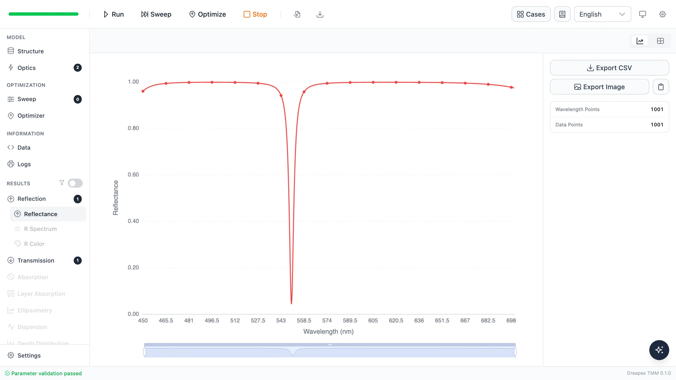
Reflectance resonance minimum inside the DBR stopband
Transmittance reaches 95.742% at 550.00 nm. With zero absorption, the reflectance minimum and transmission maximum are complementary and still satisfy $R+T=1$.
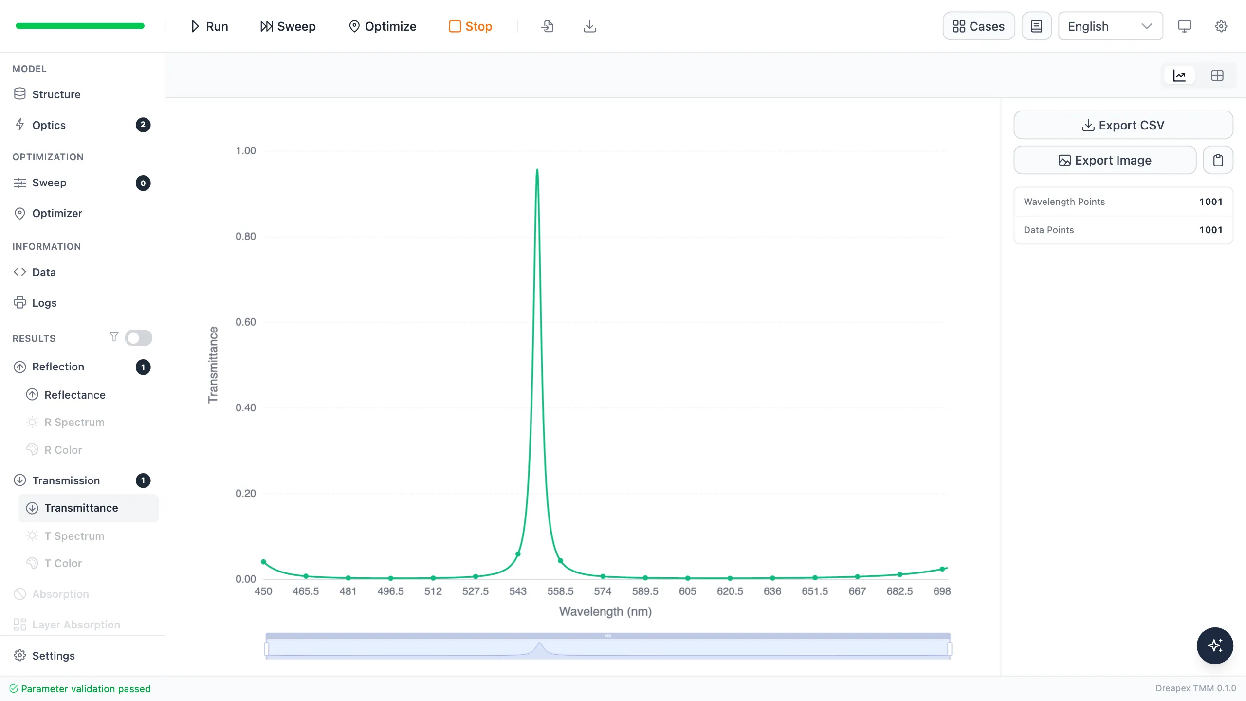
Transmittance resonance peak near 550 nm
Validate with FWHM and Q Factor
Section titled “Validate with FWHM and Q Factor”The full width at half maximum (FWHM) is the wavelength separation between the two points where transmittance falls to half its peak value. Linear interpolation between adjacent samples gives a left crossing at 548.194 nm and a right crossing at 551.817 nm, so
$$ \Delta\lambda=\lambda_R-\lambda_L=3.623\ \mathrm{nm}. $$
Here, $\Delta\lambda$ is the FWHM, while $\lambda_L$ and $\lambda_R$ are the left and right half-maximum wavelengths. The quality factor is
$$ Q=\frac{\lambda_{\mathrm{peak}}}{\Delta\lambda}=151.8, $$
where $Q$ is dimensionless, $\lambda_{\mathrm{peak}}=550.00\ \mathrm{nm}$ is the peak wavelength, and $\Delta\lambda$ is the FWHM above. A higher $Q$ means a narrower peak relative to its center wavelength.
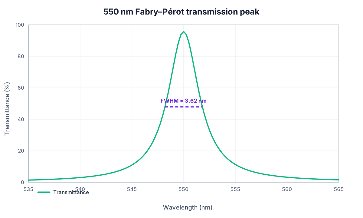
Transmission peak, half-maximum crossings, and FWHM
| Metric | Result | Tutorial criterion |
|---|---|---|
| Peak wavelength | 550.00 nm | Matches the design wavelength |
| Peak transmittance | 95.742% | High transmission of the target color |
| FWHM | 3.623 nm | Narrowband selection is present |
| Q factor | 151.8 | Consistent with the measured linewidth |
Variation Exercise
Section titled “Variation Exercise”Change only the MgF₂ cavity thickness from 199.28 nm to 205 nm. Predict whether the transmission peak moves to a shorter or longer wavelength, then run and record its position. The next tutorial, Fabry–Pérot Sensitivity Analysis, converts this shift into a thickness tolerance.
A practical narrowband filter also requires checks of angular peak shift, material absorption, and mirror asymmetry.
← Back to Tutorial Catalog · Next: How Do Thickness Errors Shift a Filter?
Going further
Section titled “Going further”These tutorials cover the operating steps only. The physics behind them, the full parameter reference for each feature, how to read the results, and the algorithm validation all live on the documentation site:
- Transfer-Matrix Method — the physics and formulas behind these tutorials
- Feature Guide — complete reference for every screen and parameter
- Results — how to read each kind of output
- Open Dreapex TMM — build and simulate in the browser