Split One Beam into Equal Halves: Design a 45° 50/50 Dielectric Beamsplitter
This tutorial designs a 45° dielectric beamsplitter for a 633 nm laser so that the reflected and transmitted powers are close to 50/50. Devices of this kind are used in interferometers, laser metrology, and dual-channel imaging. Intuitively, the coating redistributes reflected and transmitted optical power so that one beam leaves in two directions.
You will express the required reflectance as an optimization objective, then use R/T/A, s/p polarization, and an angle sweep to determine the design’s operating range.
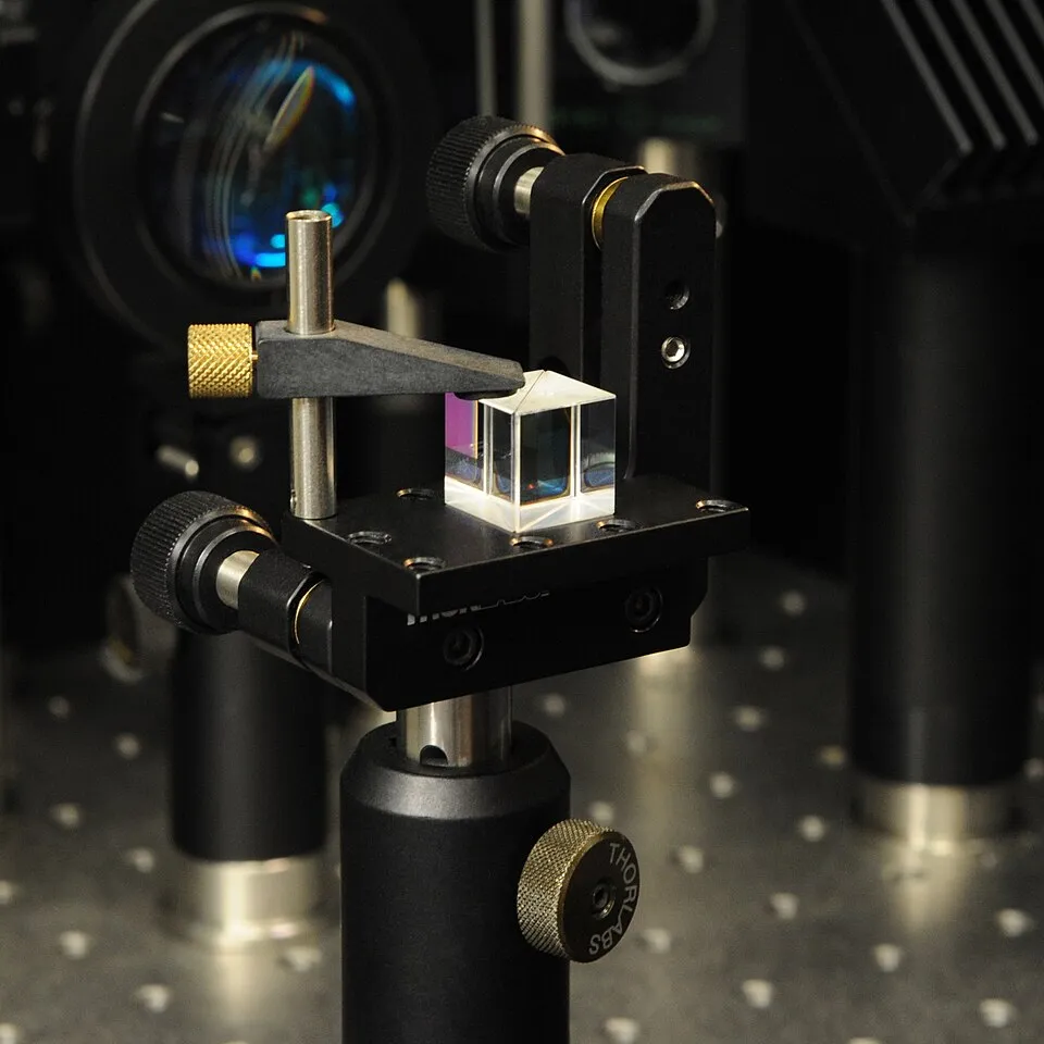
A cube beamsplitter on an optical table (Source: Geek3 / Wikimedia Commons · License: CC BY-SA 4.0)

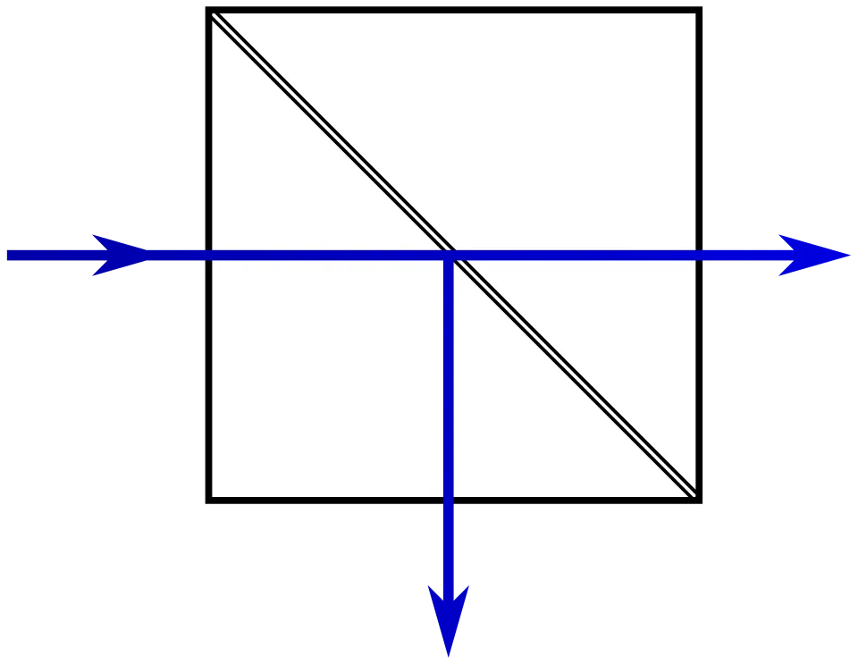
A beamsplitter produces reflected and transmitted output directions (Source: Benjamin D. Esham / Wikimedia Commons · License: Public Domain)

In the diagram, the incident beam divides into reflected and transmitted directions at the splitting surface. In this tutorial, 50/50 means that the two output powers are equal.
Express the device requirement numerically
Section titled “Express the device requirement numerically”| Item | Teaching specification |
|---|---|
| Design wavelength | 633 nm |
| Incidence angle | 45° |
| Design polarization | Unpolarized, pRatio=0.5 |
| Power target | $R=50%$, $T=50%$ |
| Allowed error | $\lvert R-50%\rvert\leq1$ percentage point |
| Additional acceptance checks | s/p polarization, 0–60° angle sweep, energy conservation |
A lossless structure satisfies
$$ R+T+A=1. $$
Here, $R$, $T$, and $A$ are the reflected, transmitted, and absorbed fractions of optical power, respectively. All materials in this tutorial are defined as nonabsorbing, so $A=0$. Achieving $R=0.5$ at the design point therefore also gives $T=0.5$.
The software uses $p$ to denote the p-polarized power fraction, or pRatio. The reflectance of a polarization mixture is
$$ R(p)=(1-p)R_s+pR_p. $$
Here, $R_s$ and $R_p$ are the reflectances for pure s and pure p polarization, respectively, and $p$ ranges from 0 to 1. A value of $p=0.5$ represents an equal-power mixture of the two polarizations. Transmittance is weighted in the same way.
Control the reflected amplitude with three layers
Section titled “Control the reflected amplitude with three layers”The structure is Air / TiO₂ / SiO₂ / TiO₂ / BK7 / Air. The BK7 substrate is 1 mm thick and is set as an incoherent layer.
| Layer | Refractive index | Initial thickness | Status |
|---|---|---|---|
| TiO₂ Top | 2.45 | 30 nm | Optimization variable |
| SiO₂ Mid | 1.46 | 50 nm | Fixed |
| TiO₂ Inner | 2.45 | 30 nm | Optimization variable |
| BK7 Substrate | 1.52 | 1 mm | Incoherent, fixed |

Initial beamsplitter structure
The one-way phase thickness of layer $i$ at oblique incidence is
$$ \delta_i=\frac{2\pi n_id_i\cos\theta_i}{\lambda}. $$
Here, $\delta_i$ is the phase thickness of layer $i$, $n_i$ is its refractive index, $d_i$ is its physical thickness, $\theta_i$ is the propagation angle inside the layer, and $\lambda$ is the vacuum wavelength. The two TiO₂ layers occupy different optical environments, so they are assigned separate variables rather than being constrained to the same thickness.
This tutorial uses constant refractive indices to create an easily reproducible model. A practical device requires wavelength-dependent n and k data for the materials.
Run the baseline
Section titled “Run the baseline”In Optics, set 400–900 nm with a 1 nm step, 45° incidence, and pRatio=0.5. Enable Reflectance, Transmittance, and Absorptance. The broad wavelength range shows the spectrum, while the optimization objective uses only 633 nm.
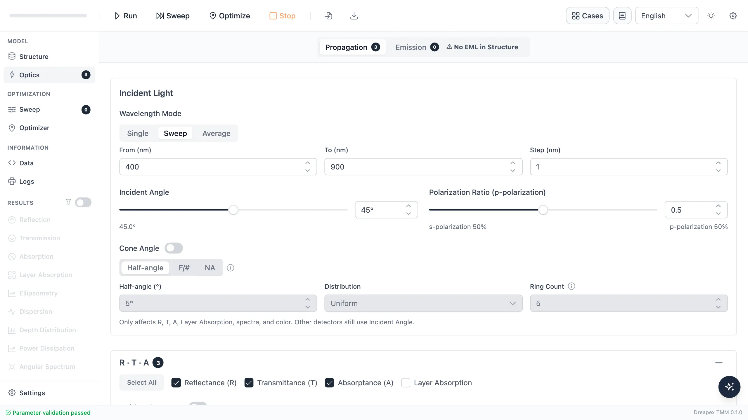
Optical conditions for the beamsplitter
At 633 nm, the initial structure gives $R=12.883%$ and $T=87.117%$. It behaves more like an antireflection structure and does not yet split the power equally.
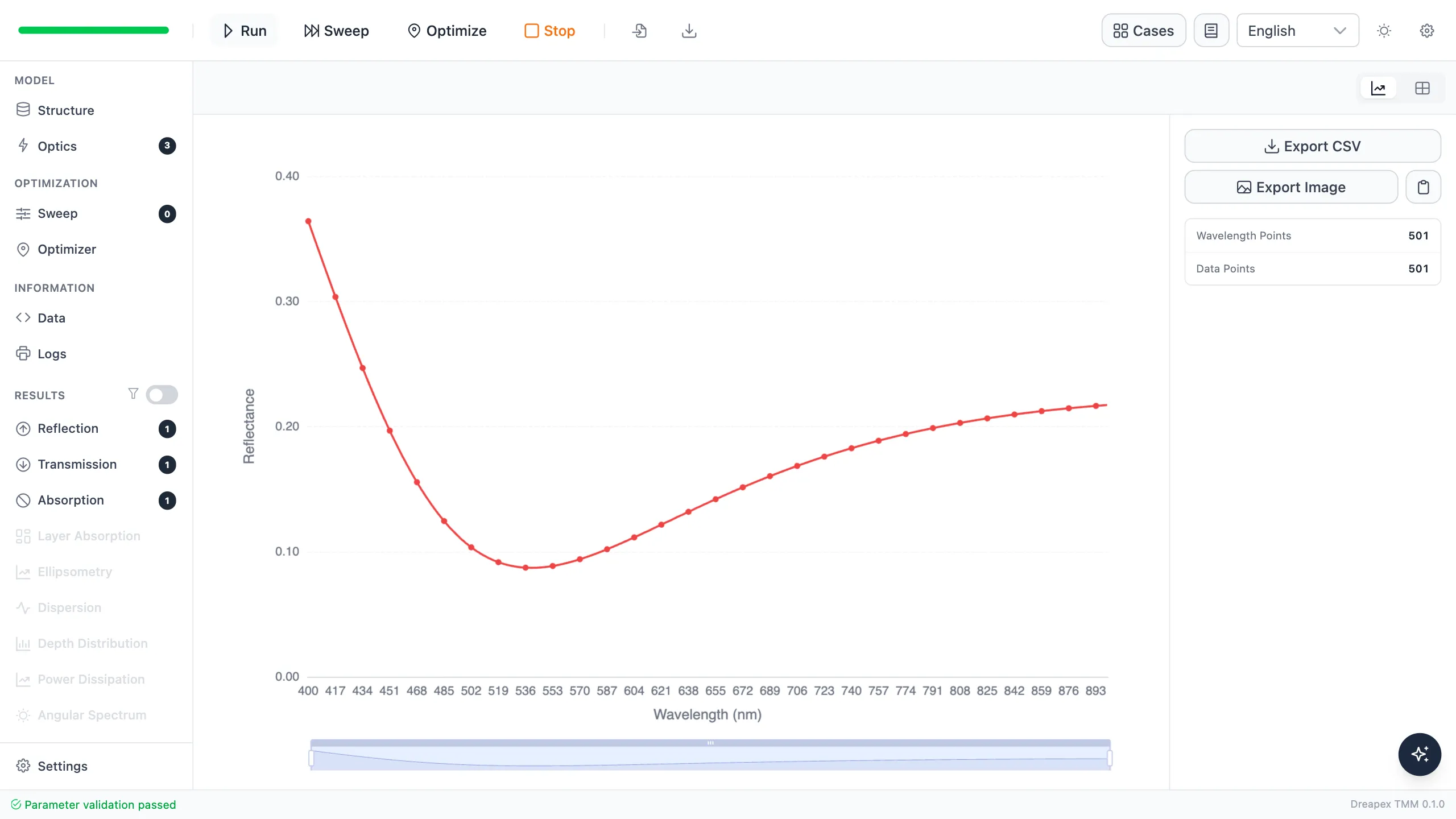
The initial structure is transmission-dominant
Set 50% reflectance as the optimization objective
Section titled “Set 50% reflectance as the optimization objective”In Optimizer, add a target-value objective that makes Reflectance approach 0.5 at 633 nm, 45° incidence, and pRatio=0.5. Adjust only the two TiO₂ layers:
The baseline calculation uses the actual 30 nm thicknesses in Structure. At the optimization stage, set each variable’s Initial Value to 60 nm. This value is the local-search starting point when Grid is disabled; it does not rewrite the recorded baseline result. With Grid enabled here, the software uses grid candidates as the starting points instead.
| Variable | Minimum | Start | Maximum |
|---|---|---|---|
| TiO₂ Top | 15 nm | 60 nm | 150 nm |
| TiO₂ Inner | 15 nm | 60 nm | 150 nm |
Use TRF with at most 120 evaluations. Enable a 7 × 7 Grid and send the best 3 starting points to local optimization.

The 50% reflectance objective and thickness variables
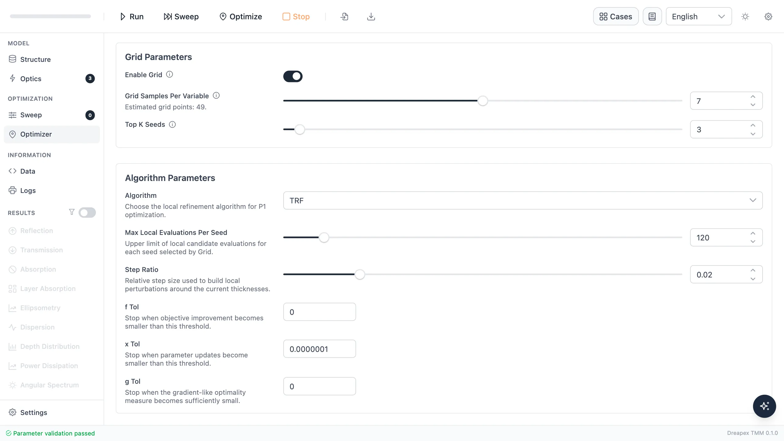
Grid seeds and TRF algorithm settings
This optimization uses 53 objective evaluations and 27 iterations to obtain:
- TiO₂ Top: 82.912 nm;
- TiO₂ Inner: 60.967 nm;
- Unpolarized reflectance at 633 nm: 49.9986%.
Click Apply to Structure, then return to Structure and confirm that both thicknesses have been updated.
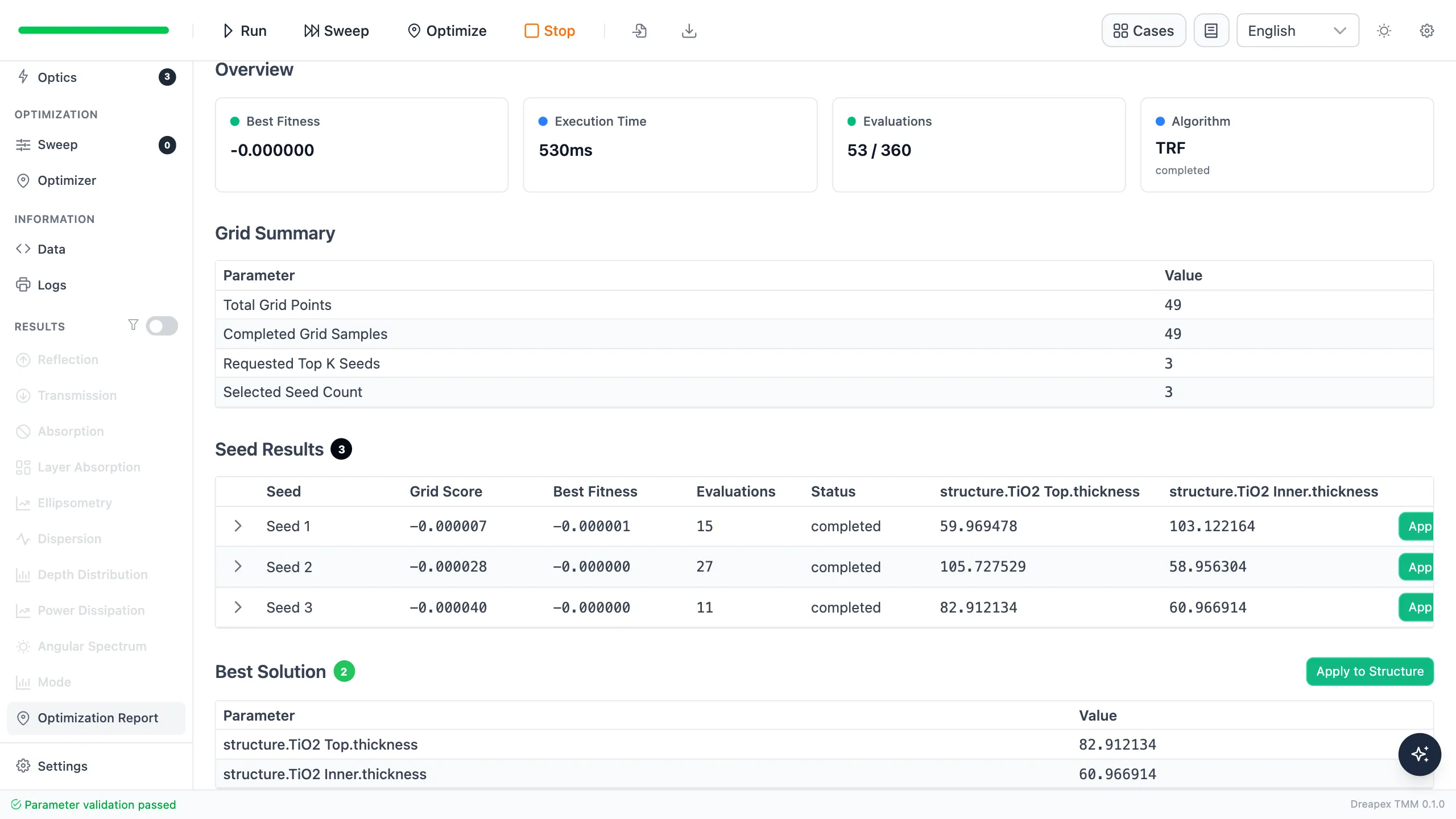
Beamsplitter optimization report

Structure after applying the optimum solution
Verify the 50/50 power split
Section titled “Verify the 50/50 power split”Run the forward calculation again after applying the optimized thicknesses.
| Design | $R(633\ \mathrm{nm})$ | $T(633\ \mathrm{nm})$ | $A$ | Deviation from 50% |
|---|---|---|---|---|
| Initial | 12.8832% | 87.1168% | 0 | 37.1168 percentage points |
| Optimized | 49.9986% | 50.0014% | 0 | 0.0014 percentage points |
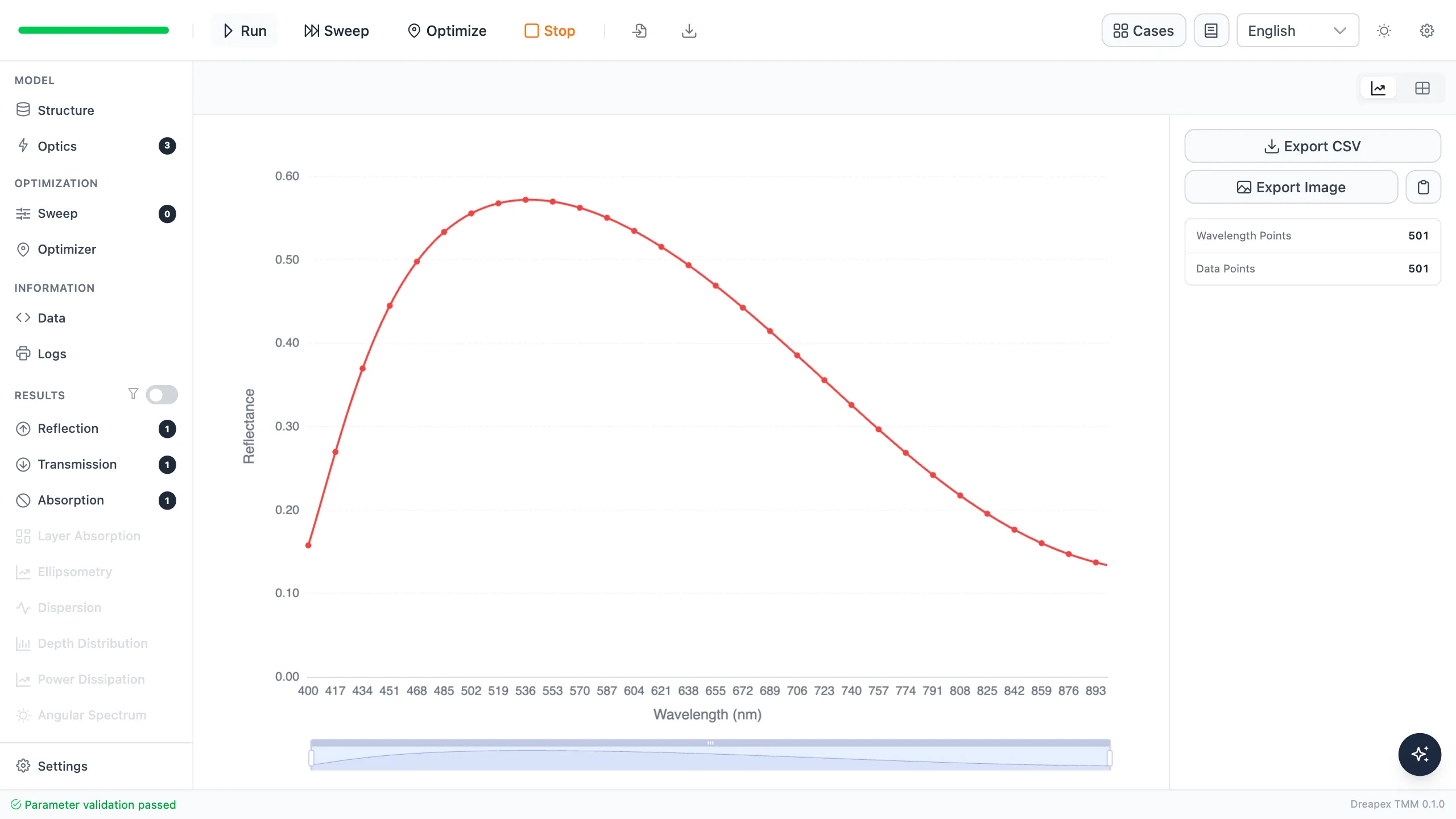
The optimized structure reaches 50% reflectance at 633 nm
The design point passes the ±1 percentage-point specification, and the energy-closure error is $1.1\times10^{-16}$.
Unpolarized 50/50 does not mean polarization-independent
Section titled “Unpolarized 50/50 does not mean polarization-independent”Keep the wavelength at 633 nm and the incidence angle at 45°, then set pRatio to 0 and 1 in turn.
First set pRatio to 0, confirm that the interface shows 100% s polarization, and run the reflectance calculation.
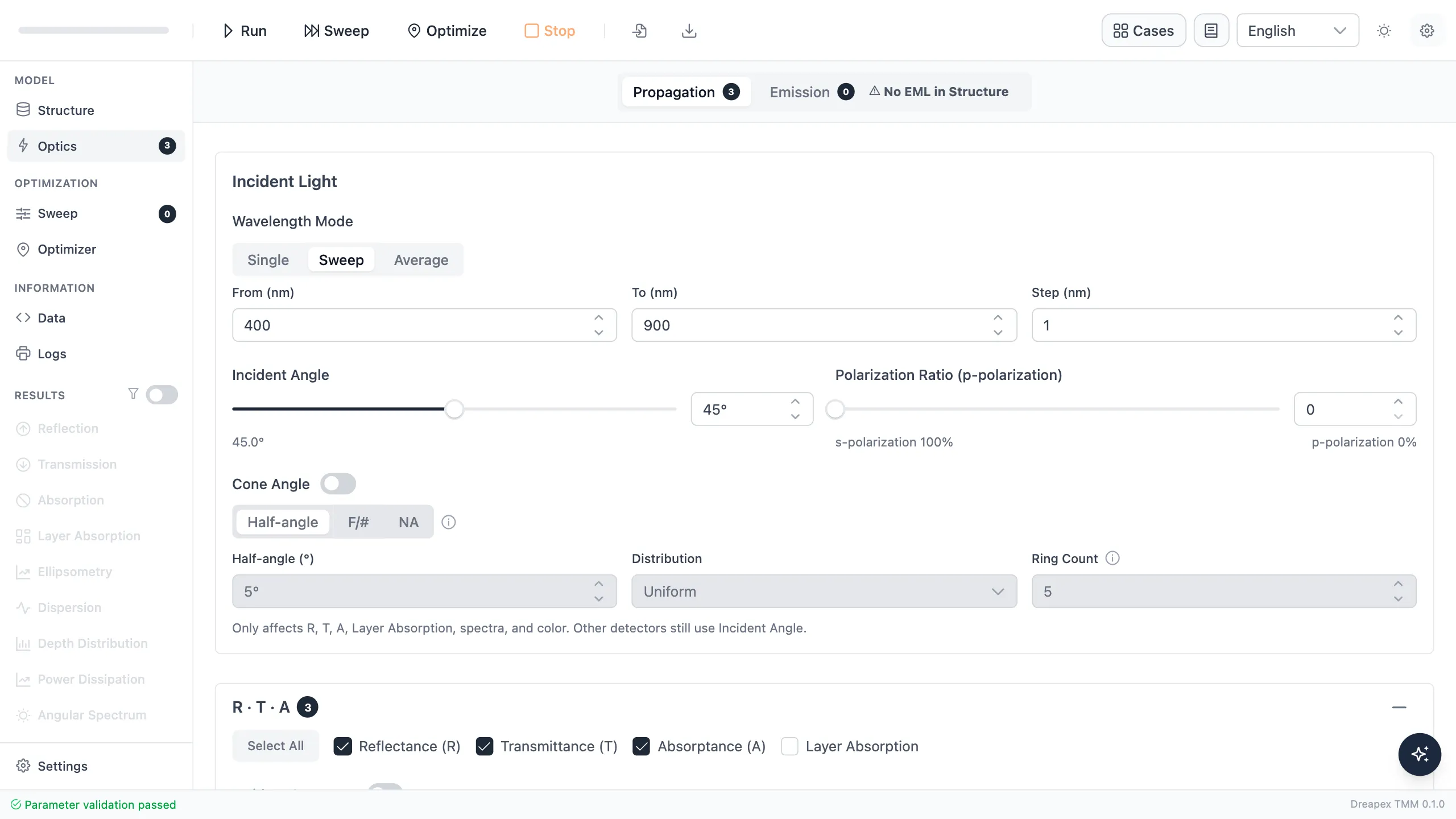
Optics settings for pure s polarization
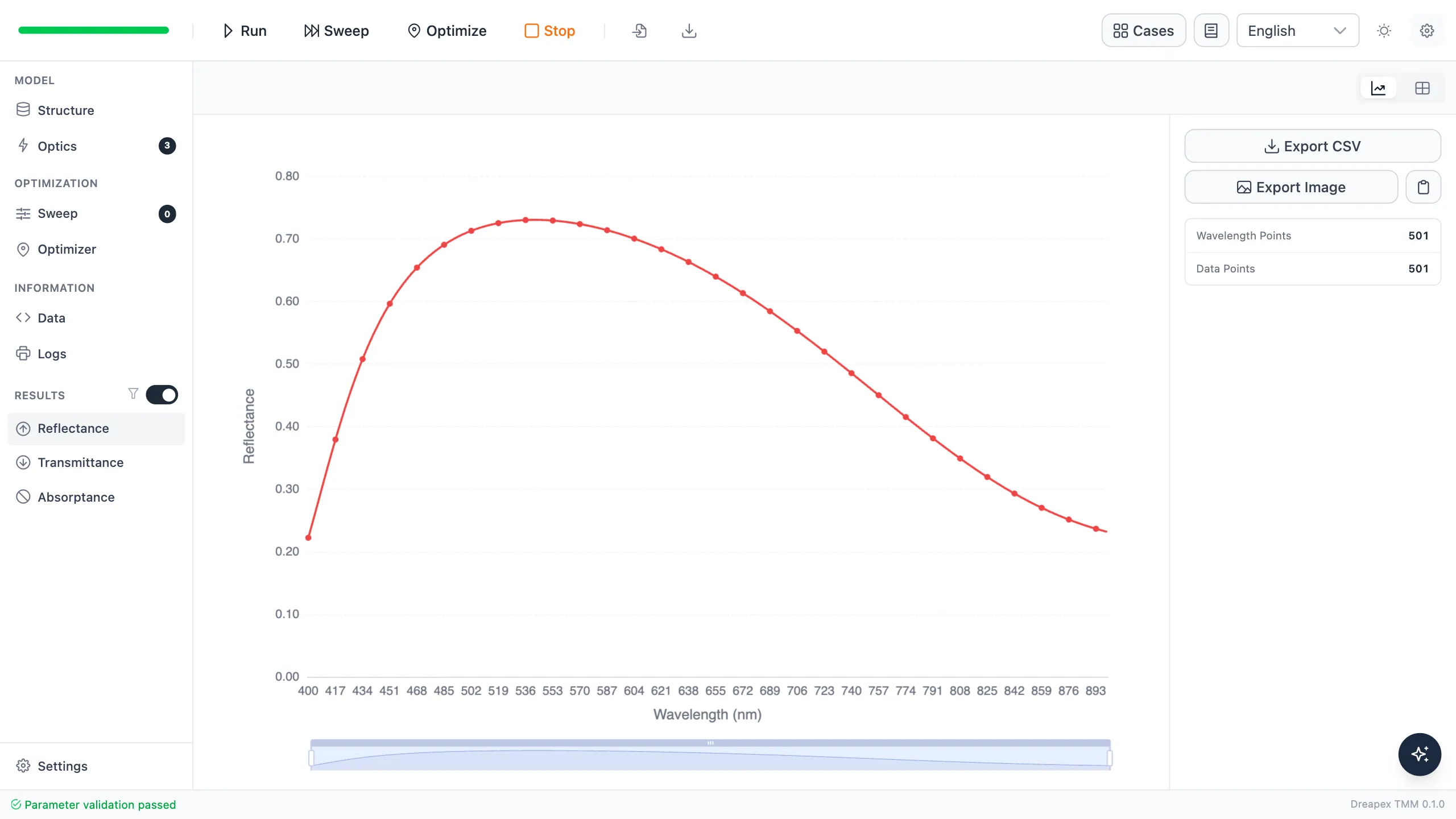
Pure s-polarized reflectance is above 50%
Then set pRatio to 1, confirm that the interface shows 100% p polarization, and rerun the same structure.
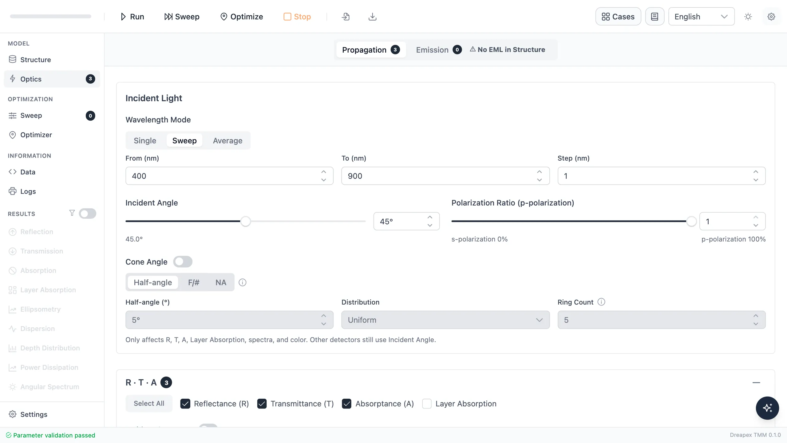
Optics settings for pure p polarization
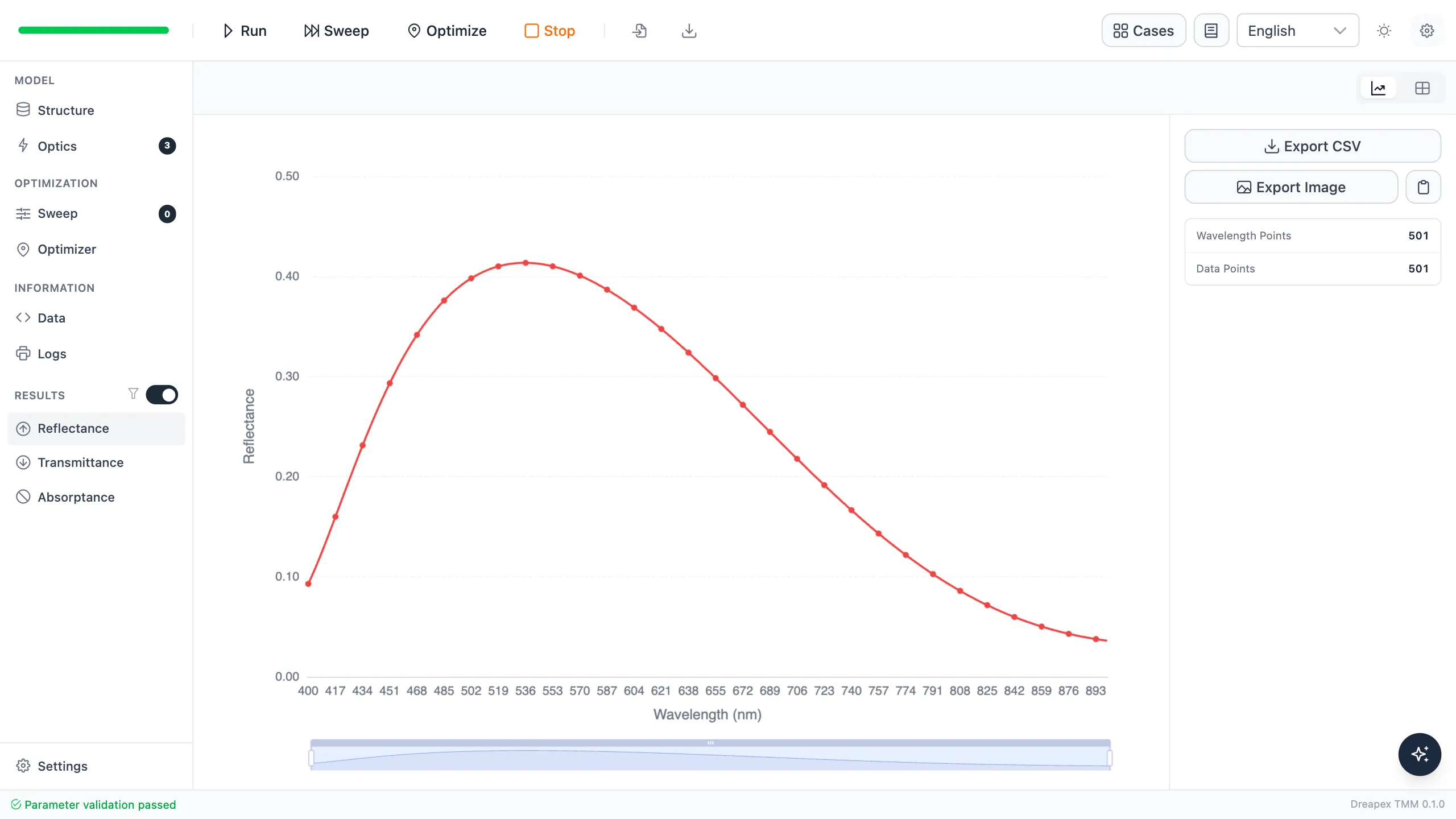
Pure p-polarized reflectance is below 50%
| Polarization | $R$ | $T$ | Deviation from 50% |
|---|---|---|---|
| s | 66.9115% | 33.0885% | 16.9115 percentage points |
| p | 33.0858% | 66.9142% | 16.9142 percentage points |
| Unpolarized average | 49.9986% | 50.0014% | 0.0014 percentage points |
The unpolarized result is close to 50% because s polarization is above 50% and p polarization is below 50%, so their equal-power average cancels the difference. This structure is a 50/50 beamsplitter only in the unpolarized-average sense; it is not a polarization-independent beamsplitter.
If the application requires any linear polarization to remain close to 50/50, create separate s and p objectives and add layers or release more independent thickness variables.
Determine the operating range with an angle sweep
Section titled “Determine the operating range with an angle sweep”Fix the wavelength at 633 nm. In Sweep, scan 0–60° in 5° steps while keeping pRatio=0.5.

Incidence-angle sweep of the splitting ratio
After running Sweep, reflectance falls gradually from about 57% to about 45% and crosses 50% near 45°.
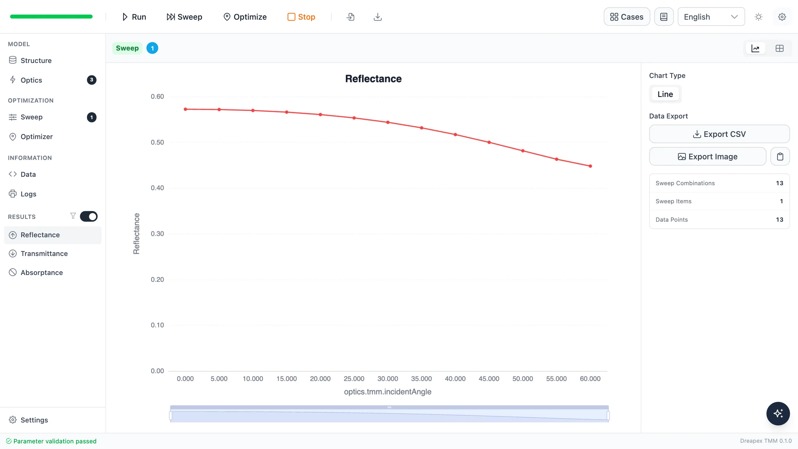
Reflectance versus incidence angle at 633 nm
| Incidence angle | $R$ | $T$ | Deviation from 50% |
|---|---|---|---|
| 0° | 57.232% | 42.768% | 7.232 percentage points |
| 30° | 54.370% | 45.630% | 4.370 percentage points |
| 40° | 51.697% | 48.303% | 1.697 percentage points |
| 45° | 49.999% | 50.001% | 0.001 percentage points |
| 50° | 48.145% | 51.855% | 1.855 percentage points |
| 60° | 44.801% | 55.199% | 5.199 percentage points |
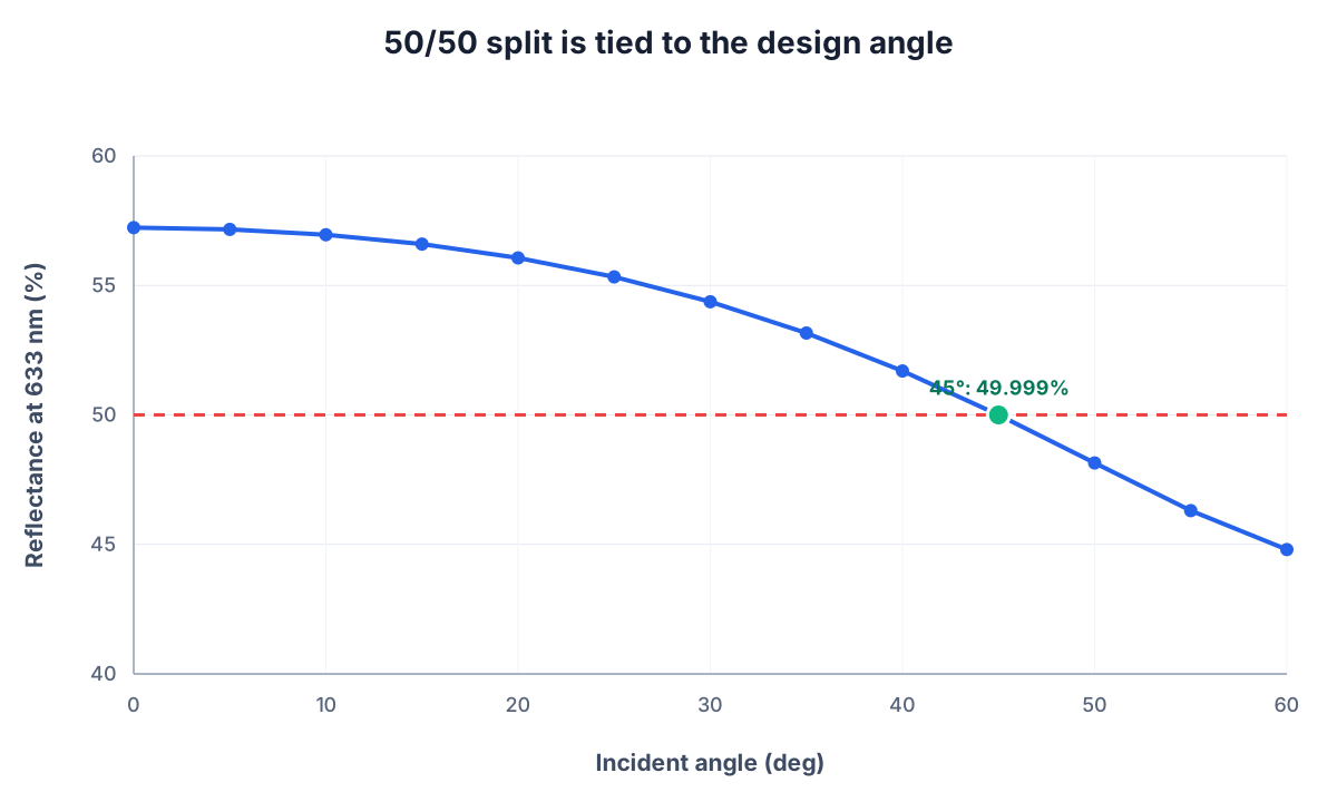
The 50/50 split occurs only near the design angle
In the coarse 5° sweep, only the 45° sample meets the ±1 percentage-point specification. This result does not define a continuous angular tolerance. To determine the passing interval, repeat the sweep near 45° with a step of 1° or smaller.
Design limits
Section titled “Design limits”The current structure achieves a 50/50 power split at 633 nm, 45° incidence, and unpolarized illumination, but it does not simultaneously satisfy broadband, wide-angle, arbitrary-polarization, or phase requirements.
| Application requirement | Additional design condition |
|---|---|
| Polarization-independent splitting | Constrain s and p separately |
| Wide-angle splitting | Create objectives at multiple incidence angles |
| Broadband splitting | Replace the single-wavelength objective with a target band |
| Real glass plate | Use actual dispersion and include the rear surface or a wedge model |
| Interferometer | Continue by checking reflection and transmission phases and both arm lengths |
Variation Exercise
Section titled “Variation Exercise”Refine the angle sweep to 40–50° with a 1° step while keeping the structure and wavelength unchanged. Find the continuous interval that satisfies $\lvert R-50%\rvert\leq1$ percentage point and compare it with the conclusion from the 5° coarse sweep.
← Back to Tutorial Catalog · Next: Separate Blue-Green and Red Light
Going further
Section titled “Going further”These tutorials cover the operating steps only. The physics behind them, the full parameter reference for each feature, how to read the results, and the algorithm validation all live on the documentation site:
- Transfer-Matrix Method — the physics and formulas behind these tutorials
- Feature Guide — complete reference for every screen and parameter
- Results — how to read each kind of output
- Open Dreapex TMM — build and simulate in the browser