Introduction
Dreapex TMM is an online optical simulation platform for planar multilayer structures. It calculates two physical processes:
- Propagation of external light through multilayers (optical coatings, filters, photodetectors, photovoltaics, and related devices).
- Outward emission from sources inside a layer (OLEDs, QLEDs, PeLEDs, and related devices).
For a planar multilayer structure, open Dreapex TMM in a browser and define the materials, layer order, and thicknesses to calculate spectra, field distributions, emission, and optical loss.

An intuitive workspace for fast simulation setup
Four Core Application Areas
Section titled “Four Core Application Areas”Optical Coatings and Filters
Section titled “Optical Coatings and Filters”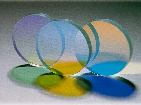
Interference filters (Source: NASA / JPL / Wikimedia Commons · License: Public Domain (NASA))


Antireflection coatings, high reflectors, beamsplitters, bandpass filters, and narrowband filters: compare reflection, transmission, and absorption across wavelength, angle, and polarization to verify passbands, stopbands, and cut-off edges. More scenarios.
Photovoltaic and Photodetector Devices
Section titled “Photovoltaic and Photodetector Devices”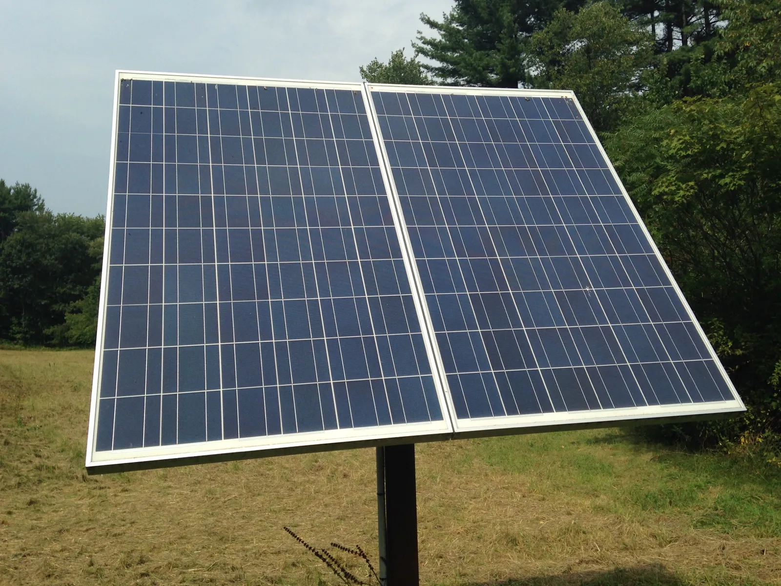
Photovoltaic modules (Source: MarkBuckawicki / Wikimedia Commons · License: CC0 1.0)

Solar cells, photodiodes, and multilayer detectors: calculate layer absorption, electric field, energy flow, and absorption density to separate active-layer contribution from parasitic loss. More scenarios.
OLED, QLED, and PeLED Devices
Section titled “OLED, QLED, and PeLED Devices”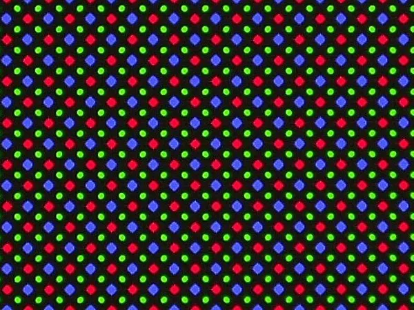
AMOLED emissive subpixels (Source: Bautsch / Wikimedia Commons · License: CC0 1.0)

Bottom- and top-emitting OLEDs, QLEDs, and PeLEDs: calculate emission spectra, angular distributions, viewing-angle color shift, and power channels to locate waveguide, surface-plasmon, absorption, and non-radiative losses. More scenarios.
Thin-Film Metrology and Optical Sensing
Section titled “Thin-Film Metrology and Optical Sensing”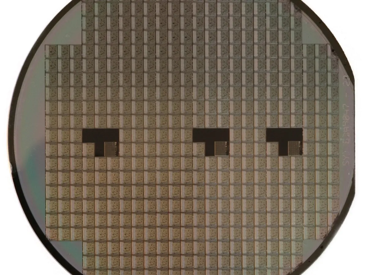
Silicon wafer (Source: Inductiveload / Wikimedia Commons · License: Public Domain)

Ellipsometry, film-thickness retrieval, and resonant sensors: calculate Ψ, Δ, and resonance wavelength to evaluate changes in thickness, material properties, or ambient refractive index. More scenarios.
Simulation Result Examples
Section titled “Simulation Result Examples”Reflectance, Transmittance, and Absorptance Spectra
Section titled “Reflectance, Transmittance, and Absorptance Spectra”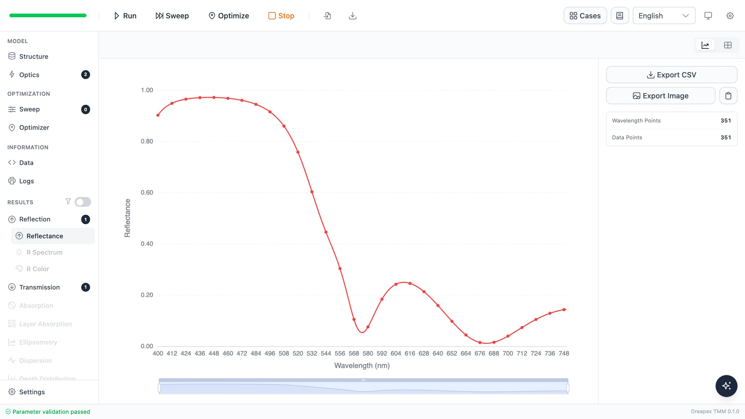
Reflectance spectrum of a 45° dichroic beamsplitter
Layer Absorption and Internal Fields
Section titled “Layer Absorption and Internal Fields”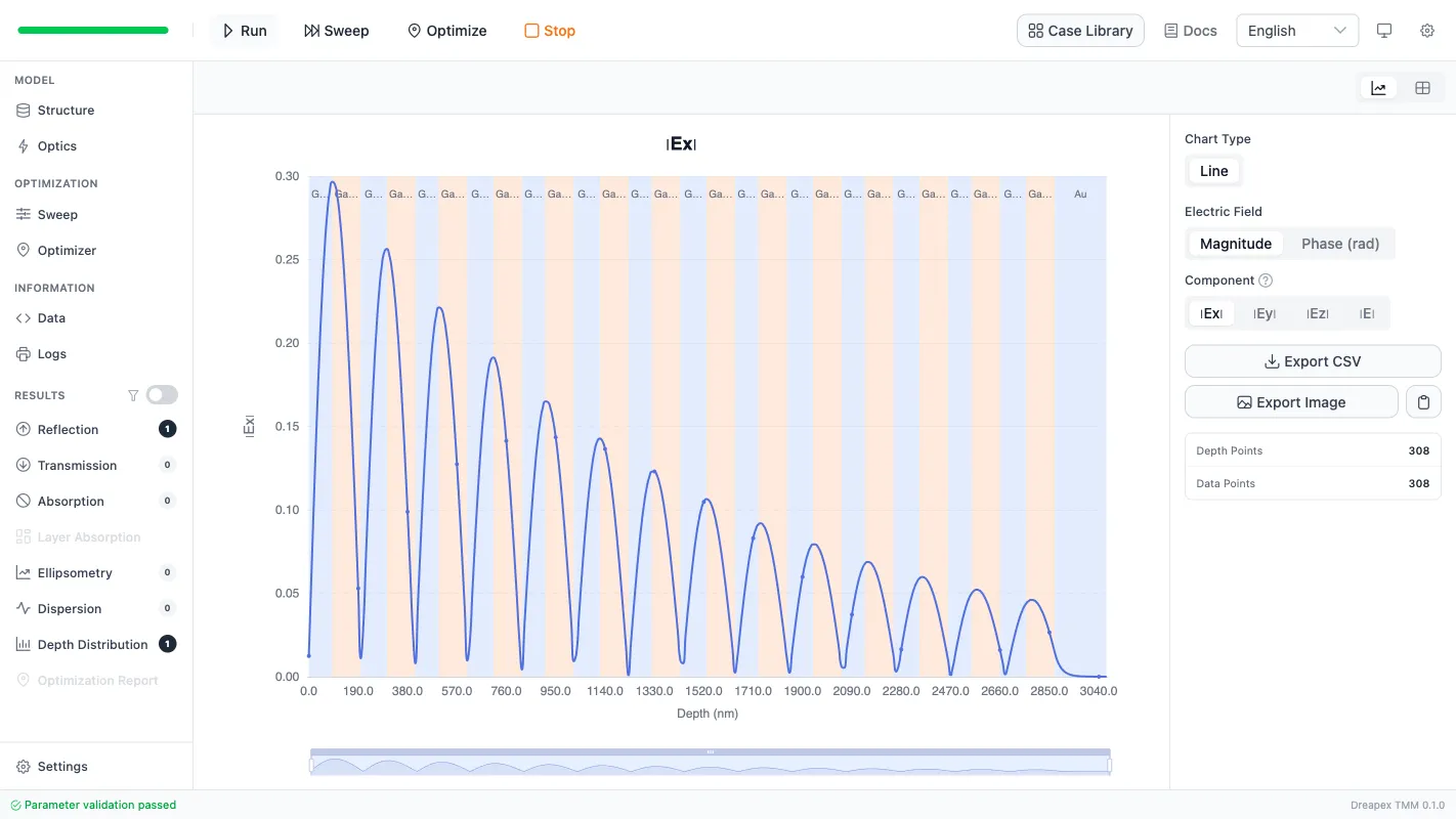
Localized electric field at a metal–DBR interface
Emission Spectra and Angular Distribution
Section titled “Emission Spectra and Angular Distribution”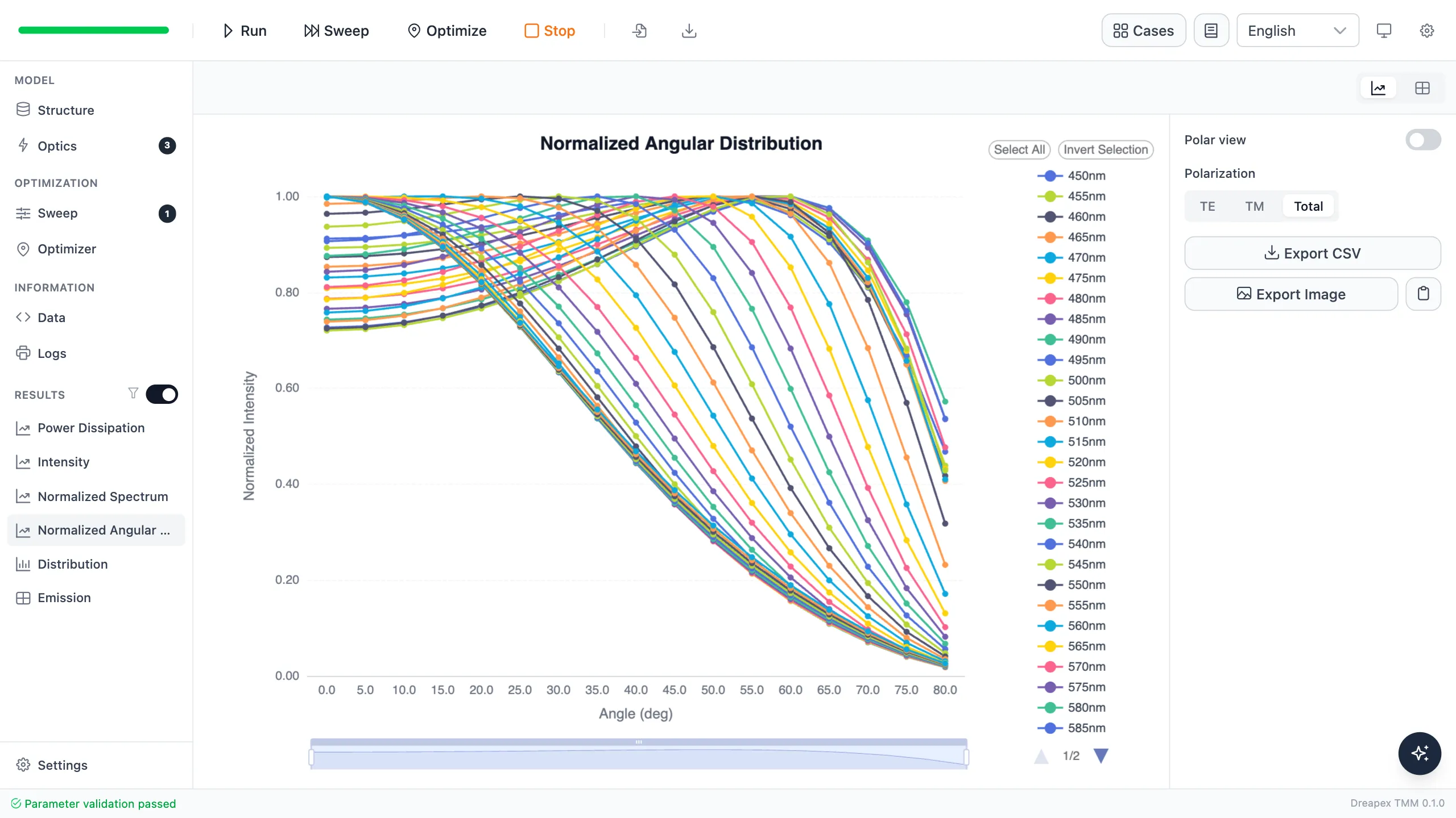
Angular emission distribution of a top-emitting OLED
Optical Modes and Loss Fractions
Section titled “Optical Modes and Loss Fractions”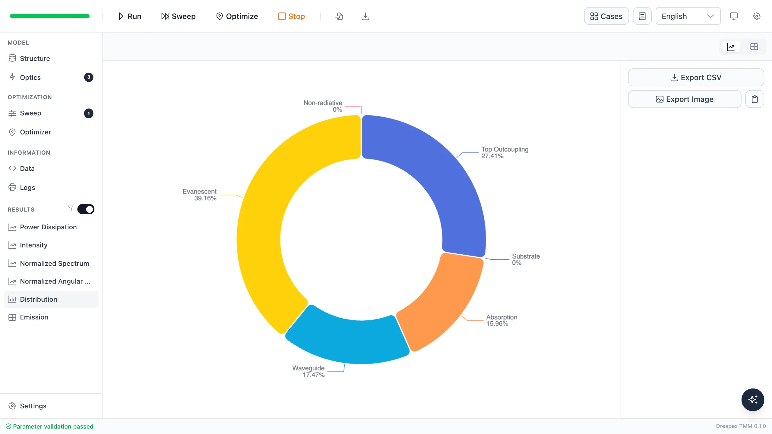
Optical modes and loss fractions of an OLED
From Results to Design
Section titled “From Results to Design”Sweeps show how results change with a parameter; optimization finds the best design for a specified target.
Parameter Sweep
Section titled “Parameter Sweep”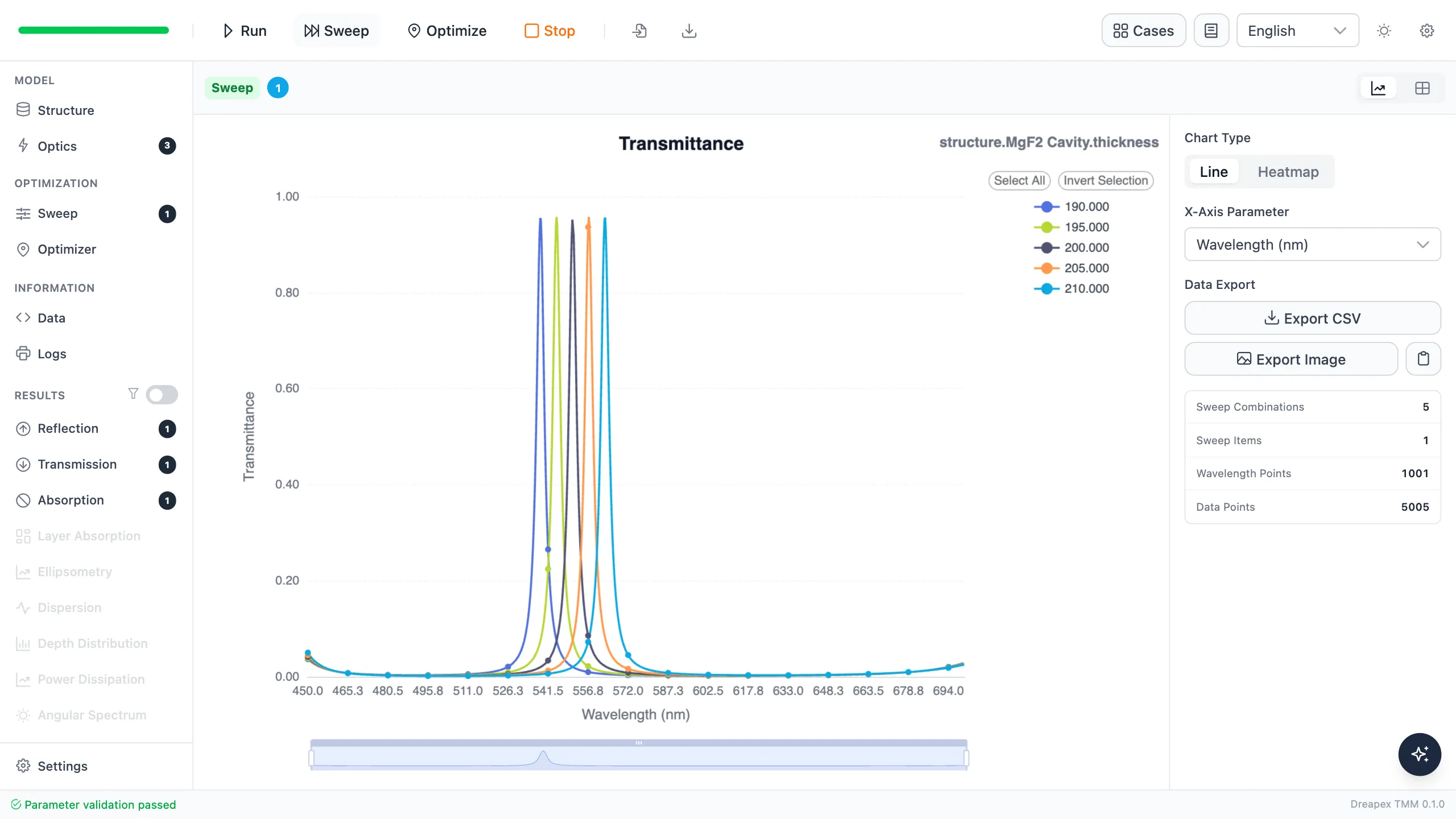
Transmission peak shift during a cavity-thickness sweep
Target-Driven Optimization
Section titled “Target-Driven Optimization”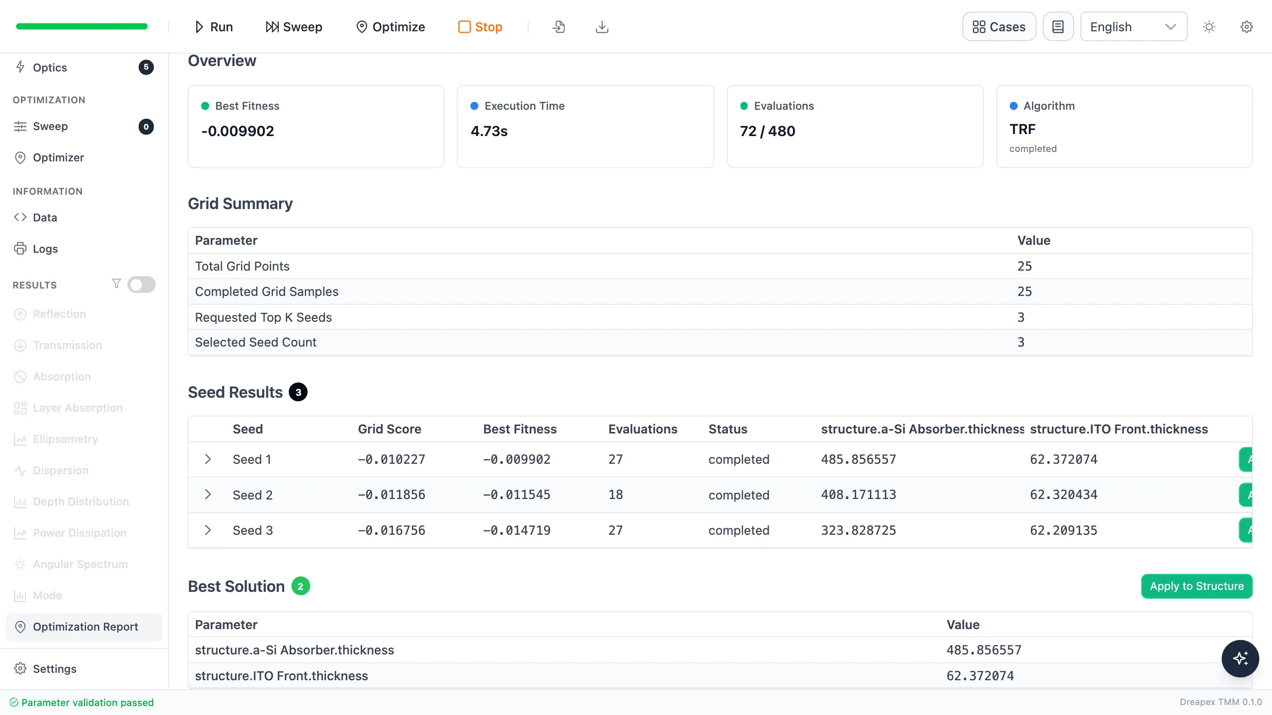
Solar-cell absorption optimization report
Open Dreapex TMM and run your first simulation.
Going further
Section titled “Going further”These tutorials cover the operating steps only. The physics behind them, the full parameter reference for each feature, how to read the results, and the algorithm validation all live on the documentation site:
- Transfer-Matrix Method — the physics and formulas behind these tutorials
- Feature Guide — complete reference for every screen and parameter
- Results — how to read each kind of output
- Open Dreapex TMM — build and simulate in the browser